Switch Block

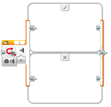
The Switch block is a container that can contain two or more sequences of programming blocks. Each sequence is called a Case. A test at the beginning of the Switch determines which Case will run. Only one Case will run each time the Switch is executed.
The Switch test shown here can decide which Case to run based on a sensor data value or a value from a Data Wire. After one Case is selected and run, the program continues with any blocks after the Switch.

Example
The program below makes a robot say “Touch” and then tests to see if the Touch Sensor is pressed. If so, the True (top) Case executes, and the robot will display “Thumbs up” and say “Yes”. If the Touch Sensor is not pressed, the False (bottom) Case executes, and robot will display “Thumbs down” and say “No”. After the Switch, the robot will say “Thank you”.
Example
True Case
False Case

The Touch Sensor is tested as soon as the robot finishes saying “Touch”. If the sensor is being held down at that instant, the Switch will run the True Case, otherwise it will run the False Case.
Tips and Tricks
A Switch does not wait for a sensor data value or data wire to reach a certain value. The test is run as soon as the Switch block starts, and one of the Cases is chosen and run immediately after the test.
In the program above, you can press the Touch Sensor before the test (or even before the program starts) and hold it in during the test, to make sure the Switch executes the True Case. Try seeing how long you can wait before pressing the sensor and still have the robot say “Yes”.
You can leave any Case in a Switch blank if you don’t want the robot to do anything in that situation. Try removing the two blocks from the False Case in the program above and see what happens.
Tabbed View
A Switch can display in Flat view, as shown in the example above, or in Tabbed view, as shown below. In Flat view, all of the Cases are visible in different rows. In Tabbed view, only one of the Cases is visible at a time.

You can use Tabbed view to make your program take up less space on the screen. The view does not affect the way the Switch executes.


Flat/Tabbed Selector
True Case
False Case

To toggle a Switch between the Flat and Tabbed views, click the Flat/Tabbed Selector.

To show a different Case inside a Switch in Tabbed view, click on the different tabs at the top of the Switch border.
Tips and Tricks
Blocks in all of the Cases of a Tabbed Switch are a part of your program, even if you can only see some of them at a time.
Choose the Switch Test


Mode Selector
Port Selector
Inputs

Use the Mode Selector to select the type of test that the Switch will use to choose which Case to run. You can test a sensor value or a Data Wire value.

If you select a mode that uses a port, use the Port Selector to make sure that the port matches the port on the EV3 Brick that the sensor or motor is connected to.

The Inputs available will change depending on the mode. In some modes, you can compare a sensor value to a Threshold Value, and in other modes you can test for specific sensor values. The modes are described below.
Testing a Sensor Threshold
The Switch block contains several modes that read a Numeric sensor data value and compare it to a Threshold Value to get a True or False result. For example, in the Color Sensor – Compare – Reflected Light Intensity mode, you could test whether the Reflected Light Intensity from the Color Sensor is less than 50.

In these modes, the Switch block contains two Cases. If the result of the test is True, the True Case will execute, otherwise the False Case will execute.
Tips and Tricks
The True Case is the top Case in Flat view, marked by a checkmark. The False Case is the bottom Case, marked by an “X”.
To use a mode with a sensor threshold, choose the Compare Type (for example, Less Than), and enter the Threshold Value (for example, 50) to compare the sensor data to. The Switch block will take a single sensor reading and compare it to the threshold to get a True or False result.
Example
In this program, the Switch block uses the Color Sensor – Compare – Reflected Light Intensity mode to test whether the Reflected Light Intensity is less than 50. If so, it displays “Low”, otherwise it displays “High”. The Switch is repeated in a Loop so that the display is updated continuously based on new sensor tests.
Tips and Tricks
Sensor tests happen very quickly. Without the Loop in the example above, the program would test the sensor only once and finish so quickly that you wouldn’t even notice it.
Testing for Specific Sensor Values
The following modes allow a Switch to test for specific sensor values. You can create two or more Cases in the Switch that correspond to different values that you want to test for, and the Switch will select the matching Case.
ModeUseSee
Brick Buttons – Measure - Brick Buttons Choose between two or more Cases depending on which Brick Button is pressed.Using the Brick Buttons
Brick Buttons – Compare - Brick Buttons Choose between two Cases depending on whether one of the selected Brick Buttons is Pressed, Released, or Bumped.Using the Brick Buttons
Color Sensor – Measure - Color Choose between two or more Cases depending on which color is detected.Using the Color Sensor
Color Sensor – Compare - Color Choose between two Cases depending on whether or not one of the selected colors is detectedUsing the Color Sensor
Infrared Sensor – Measure - Remote Choose from two or more Cases depending on which button(s) are pressed on the IR Beacon.Using the Infrared Sensor Remote Mode
Infrared Sensor – Compare - Remote Choose between two Cases depending on whether a specified button on the IR Beacon is pressed (or whether one of a set of specified buttons is pressed).Using the Infrared Sensor Remote Mode
Touch Sensor - Compare - State Choose between two Cases depending on whether the Touch Sensor is Pressed or not, Released or not, or Bumped or not.Using the Touch Sensor
Ultrasonic Sensor – Compare - Presence/Listen Choose between two Cases based on whether an ultrasonic signal is detected in “listen only” mode.Using the Ultrasonic Sensor
Messaging Choose between two Cases based on a message value.Messaging
Testing for Multiple Values
The sensor Measure modes of the Switch block allow you to specify several (two or more) different sensor values to test for. You can give each value a different Case in the Switch. For example, in the Color Sensor – Measure – Color mode, you could test for Black, White, and Red, and create three different Cases, one for each color.


Add Case
Case Value
Default Case
Remove Case

To use multiple Cases in a sensor Measure mode, click the Add Case button to create the number of Cases you want. For each Case, click the Case Value to select a value for the sensor from the list. You can click the Remove Case button to remove a case.

Click the Default Case button to mark one Case as the Default Case. The Default Case is executed when the sensor detects a value that does not match any of the Cases in the Switch.

See Programming Example: Say “Red”, “Green”, and “Blue” when Detected in Using the Color Sensor.

See Programming Example: A Brick Buttons Control Panel in Using the Brick Buttons.
Testing a Value from a Data Wire
In the Logic, Text, and Numeric modes, the Switch can choose which Case to execute based on an input value from a Data Wire.
Modes
Logic Mode
In the Logic mode, a Switch chooses between a True Case and a False Case based on the value of the Logic input. You could connect a Logic output from any programming block to the Logic input using a Data Wire.

Programming Example: See the Compare Block.
Text Mode
In the Text mode, the Switch compares the value of the Text input to two or more Text values that you specify, with a Case for each value. The Case that has a value that matches the Text input will execute. If no values match, the Default Case will execute.

See Testing for Multiple Values above for information on creating multiple Cases. Each Case in Text mode will have a Text value that you can type directly into its Case Value.
Example
In this example, a Switch in Text mode uses the output from a Messaging block to choose between three different Cases, depending on which message is received.
Numeric Mode
In the Numeric mode, the Switch compares the value of the Number input to two or more Numeric values that you specify, with a Case for each value. The Case that has a value that matches the Number input will execute. If no values match, the Default Case will execute.

See Testing for Multiple Values above for information on creating multiple Cases. Each Case in Numeric mode will have a Numeric value that you can enter directly into its Case Value.
Example
In this example, a Switch in Numeric mode is using the output from a Variable block to choose between three different Cases. The Default Case of the Switch is empty, so if the value of the “Action” variable is anything other than 1, 2, or 3, the Switch will do nothing.
Resizing a Switch
The Switch block will usually expand automatically to make room for new programming blocks that you drag into the Cases inside. You can also resize a Case manually if you need to. To resize a Case inside Switch in Flat view, click on the left or right border of the Switch by the Case you want to resize, then drag the Resize Handles that appear around the outside.

Tips and Tricks
In Tabbed view, all Cases display the same size. Resizing one Case to make it larger will make all Cases display in the same larger space.
Inputs
The inputs available for the Switch block will depend on the mode selected. You can enter the input values directly into the block. Alternatively, the input values can be supplied by Data Wires from the outputs of other Programming Blocks.
InputTypeNotes
Logic LogicUsed to select a Case in Logic mode
Number NumericUsed to select a Case in Numeric mode.
Text TextUsed to select a Case in Text mode.
Compare Type NumericComparison type for a mode with a Threshold Value input.
0: = (Equal)
1: ≠ (Not Equal)
2: > (Greater Than)
3: ≥ (Greater Than or Equal To)
4: < (Less Than)
5: ≤ (Less Than or Equal To)
Threshold Value NumericValue to compare sensor data to, to choose a True Case or False Case based on a Numeric sensor value.
(Inputs for individual sensor types)See the help on the individual sensor types for more information on the sensor data.
Switch
Quick links