Color Sensor Block

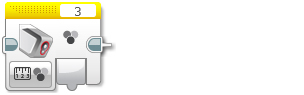
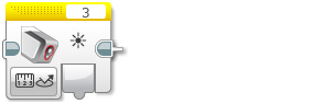
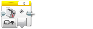
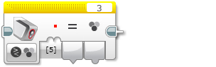
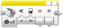
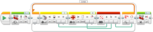
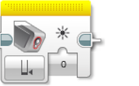
The Color Sensor block gets data from the Color Sensor. You can measure the color or intensity of light and get a Numeric output. You can also compare sensor data to an input value and get a Logic (True or False) output.

See Using the Color Sensor for more information about how the Color Sensor works, the different modes, the data provided, and programming examples.
Tips and Tricks
The Color Sensor block outputs data with a Data Wire See Using the Color Sensor for other ways to use the Color Sensor that don’t require a data wire.
Choose the Sensor Port and Mode


Port Selector
Mode Selector
Inputs
Outputs

Use the Port Selector on the top of the block to make sure that the sensor port number (1, 2, 3, or 4) matches the port on the EV3 Brick that the Color Sensor is connected to.

Use the Mode Selector to select the mode for the block. The Inputs and Outputs available will change depending on the mode.
Modes
Measure - Color


The Measure – Color mode outputs the detected color number in Color.
Measure – Reflected Light Intensity


The Measure – Reflected Light Intensity mode outputs the light intensity in Measured Value.
Measure – Ambient Light Intensity


The Measure – Ambient Light Intensity mode outputs the light intensity in Light."
Compare – Color


In the Compare – Color mode, you can select one or more colors in the Set of Colors. The Compare Result output will be True if the detected color matches any of the selected colors. The detected color is output to Color."
Compare – Light Intensity


The Compare – Reflected Light Intensity and Compare – Ambient Light Intensity modes compare the detected light intensity to the Threshold Value using the selected Compare Type. The True/False result is output in Compare Result, and the detected light intensity is output in Light."
Example 1
This program turns the Brick Status Light on in orange, and makes it pulse on and off whenever the Color Sensor detects an ambient light intensity greater than 50.
Example 2
This program makes a robot drive until the Color Sensor detects reflected light intensity < 50, or until motor B has turned 2000 degrees, whichever comes first.
Calibrate Modes
The Calibrate modes allow you to calibrate the Color Sensor from within a program. You can also manually type in the minimum and maximum value the sensor should use.
Calibrate - Minimum


The Calibrate – Minimum mode allows you to specify the minimum light intensity in the Value input. After calibration, the Color Sensor will report this light intensity as 0 or the value specified.
Calibrate - Maximum


The Calibrate – Maximum mode allows you to specify the maximum light intensity in the Value input. After calibration, the Color Sensor will report this light intensity as 100 or the value specified.
Calibrate - Reset


The Calibrate – Reset mode restores the Color Sensor calibration to its default state.
Inputs and Outputs
The inputs available for the Color Sensor block will depend on the mode selected. You can enter the input values directly into the block. Alternatively, the input values can be supplied by Data Wire from the outputs of other Programming Blocks.
InputTypeAllowed ValuesNotes
Set of Colors Numeric ArrayEach element: 0 – 7Selected color(s) to test for in Compare – Color mode:
0 = No Color
1 = Black
2 = Blue
3 = Green
4 = Yellow
5 = Red
6 = White
7 = Brown
Compare Type Numeric0 - 50: = (Equal to)
1: ≠ (Not Equal to)
2: > (Greater than)
3: ≥ (Greater than or Equal to)
4: < (Less than)
5: ≤ (Less than or Equal to)
Threshold Value NumericAny numberValue to compare sensor data to
Value Numeric0 – 100Light intensity for Calibrate modes
The outputs available will depend on the mode selected. To use an output, use a Data Wires to connect it to another Programming Block.
OutputTypeNotes
Color NumericDetected color number:
0 = No Color
1 = Black
2 = Blue
3 = Green
4 = Yellow
5 = Red
6 = White
7 = Brown
Compare Result LogicTrue/False result of a Compare mode.
Light NumericThe Light Intensity (0 to 100).
Color
Quick links